Electromagnetic Theory
Unlike optical and infrared imaging sensors which are inherently passive, meaning they rely on reflected or radiated energy, radar is an active sensor--providing its own illumination in the form of microwaves. Microwaves are electromagnetic (EM) waves in approximately the 1-1000 GHz region of the EM spectrum, as illustrated in Figure 1.
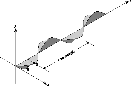
An electromagnetic wave is a self-propagating wave (requiring no medium to travel through) consisting of electric and magnetic fields whose intensities follow a sinusoidal pattern. These fields are perpendicular to each other and in phase as shown in Figure 2.
One wavelength ( ) is the distance from one crest to the next crest. The frequency (f) of
the wave is the number of crests to travel one wavelength per unit time. The
propagation velocity (or phase velocity) of the wave is dependent on the medium through
which it is traveling. It is calculated as:

where  and
and  are the permeability and
permittivity, respectively, of the medium. These are inherent electromagnetic
qualities specific to different types of matter. The lowest values these can
have are
  0 and
0 and
 0 which occur for a
vacuum (free space). Thus the maximum velocity of light is within a vacuum and
is equal to:

Air is so diffuse that within it the velocity of an EM wave can still be considered to be c. The wavelength and frequency are related to the velocity by the equation:

where v is the velocity in metres per second, f is the
frequency in Hertz (cycles per second) and  is the wavelength in metres.
The ratio of the electric field intensity E to the magnetic field intensity B at any moment is always equal to the speed of light in a vacuum.

The polarization of the EM wave refers to the direction of the electric field vector. In radar science, the wave is said to be polarized in the direction of its E vector.
Principles of Real Aperture Radar
The two main types of radar images are the circularly scanning plan-position indicator (PPI) images and the side-looking images. The PPI applications are limited to the monitoring of air and naval traffic. Remote sensing applications use the side-looking images which are divided into two types--real aperture radar (usually called SLAR for side-looking airborne radar or SLR for side-looking radar) and synthetic aperture radar (SAR).The SLAR imaging system uses a long, straight antenna mounted on a platform (aircraft or satellite), with its longitudinal axis parallel to the flight path. The antenna emits pulses of electromagnetic energy directed perpendicular to the flight path of the platform and downward to the surface of the Earth, as illustrated in Figure 3. These pulses fall within a narrow area on the ground and are scattered, usually in many directions, including the direction of the antenna. The return echoes arrive at the antenna at different times, depending on the distance from the antenna to the specific scattering object on the ground.
Range Resolution
Range is the direction perpendicular to flight path of the aircraft. The vertical beamwidth , shown in Figure 3, is determined by
the wavelength (
 ) and the antenna height
Wa such that
  v
=
v
=  / Wa. Referring to Figure 4, we see that the
width of the ground swath Wg, also called the range extent, is simply
calculated as:

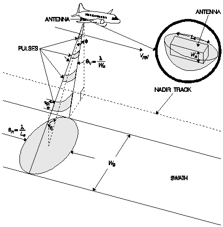
Figure 3. Geometry of a side-looking real aperture radar.
and so

where  is the incidence angle of the beam at the midpoint
of the swath (equal to the look angle
  ) and
Rm
is the slant range (distance) from the antenna to the midpoint of the swath.
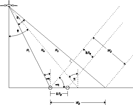
Figure 4. Range resolution of a side-looking real aperture radar.
Ground resolution is defined as the minimum distance on the ground at which
two object points can be imaged separately, shown in Figure 4 as the distance
 Rg. Two objects can be distinguished if the leading
edge of the pulse echo from the more distant object arrives at the antenna
later than the trailing edge of the pulse echo from the nearer object. Thus
if their distances to the antenna are different by at least half of the
pulse length (the distance the pulse travels in the time
 p during which the transmitter is turned on) then the
objects are resolvable. Therefore the ground range resolution is

where  Rg is the slant range resolution,
 is the incidence angle, Lp is the pulse length (in
units of distance),
  p is the pulse
duration (in units of
time) and c is the speed of light. Note that as you approach the nadir
line directly below the aircraft,
  approaches zero making
sin(
 ) approach zero so that the ground range resolution
becomes extremely poor. This makes sense since the objects near the nadir
line are all virtually the same distance from the antenna, making them
impossible to distinguish.
To achieve a ground range resolution small enough to be useful, the pulse duration çp would have to be too short to generate enough energy to produce a sufficient echo signal to noise ratio (SNR). To get around this, a technique known as pulse compression is often used together with a type of processing of the returned signal known as matched filtering (which we will not go into here, though a good description can be found in Curlander, see SAR References) to produce both high resolution and a high SNR. The ground range resolution possible with these techniques is

where BR is the frequency bandwidth of the transmitted radar pulse. The resolution can be further improved by increasing the frequency bandwidth.
Azimuth Resolution
Azimuth is the direction parallel to the flight path of the aircraft. Figure 3 shows that the angular spread of the radar beam in the azimuth direction is equal to H =
H =  /
La where
  is the wavelength of the transmitted beam and La is the length of the radar antenna in
the azimuth direction. This spread is due to interference of the waves emitted from and
received by the dipoles of the antenna, which causes the angular spread to decrease as
the aperture length increases (a longer antenna produces a tighter beam, much as a
longer barrel of a gun produces less dispersion). Two objects on the ground and with
the same slant range R can only be imaged separately if they are not both within the
radar beam at the same time. Thus the azimuth resolution is

Principles of Synthetic Aperture Radar
Because of the way in which microwaves interact with the atmosphere and the ground, only a select few frequency bands are useful for imaging. These are shown in Figure 5. The wavelength affects the penetration depth and also the size of a target necessary to return the radar. This shall be discussed later.
Figure 5. Microwave frequency bands useful for imaging.
For a specific frequency f (or wavelength  ) and
slant range R, the azimuth resolution is entirely dependent on the
aperture length La. However, for the altitudes at which
satellite or airborne imaging sensors operate (in the 1-10 GHz region),
engineering difficulties make it is impossible to achieve values of
La /
  greater than several hundred.
For example, the new Canadian satellite RADARSAT, launched in 1995, orbits
at 792 km and operates at a frequency of 5.3 GHz (C-Band). The real aperture
limit to the azimuth resolution would be

Through the use of synthetic aperture technology, however, RADARSAT can achieve a resolution as low as 9 m.
It was in 1951 that Carl Wiley first realized that the Doppler spread of the echo signal could be used to synthesize a much longer aperture (thus the name synthetic aperture radar) to greatly improve the resolution of a side-looking radar.
The Doppler Effect
When a detector moves with respect to a source of waves, a shift in frequency is observed known as the Doppler effect. When a source emitting waves with frequency f recedes from the observer at a velocity v, the observed frequency is
When the source approaches the observer, the observed frequency is

where v is always positive. Thus a receding source exhibits a lower frequency and an approaching source exhibits a higher frequency than the actual frequency emitted.
When two target points on the ground are separated in the azimuth direction, they are at slightly different angles from the antenna with respect to the line of flight. Because of this, they have slightly different speeds at any given moment relative to the antenna. Therefore the signal echoed from each target will have its frequency shifted a different amount from the original. To calculate the Doppler frequency shift for a specific target, refer to Figure 6 as we first calculate dR/dt--the relative speed with which the target and antenna approach each other.
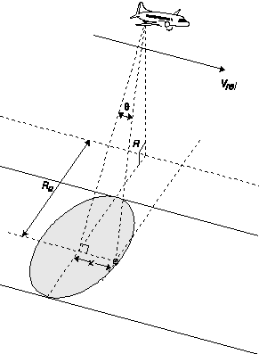
Figure 6. SAR geometry for calculating the Doppler frequency shift for a point target.
To find the R-directional component of Vrel (the velocity with which the target approaches the sensor), we can project Vrel (parallel to x) onto a line parallel to R to get

Now, we can calculate the frequency observed by the ground target:
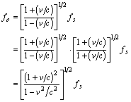
But for v << c, v2 / c2 approaches 0. Therefore

This frequency is different from the actual frequency emitted from the antenna by the amount

Since the return echo will be shifted by the same amount, the Doppler frequency shift for the target is
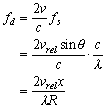
This value provides a means of determining exactly where the echo signal came from. For a return signal detected by the antenna at a time corresponding to the slant range R (t = 2R/c) and with a Doppler frequency shift of fd, the azimuth coordinate must be
 .
.
Even if another target is at range R and within the beam at the same time, measurement of its Doppler frequency shift fd still allows us to associate it with an azimuth coordinate x2. Thus for any target point, we now have two coordinates to localize it--the ground range Rg, relative to the nadir line, and the azimuth distance x2 relative to broadside.
SAR Azimuth Resolution
Utilizing the Doppler effect cannot increase the range resolution but it does greatly increase the azimuth resolution. From the equation for Doppler frequency shift, the azimuth resolution can be calculated as
where  f is the
resolution of the Doppler frequency shift--approximately equal to the
inverse of the time during which the point target was in the beam,
 fd
fd  1 / tspan.
This time span can be calculated as

Therefore the azimuth resolution is

which implies that better resolution is obtained with a smaller antenna--not what one
would expect since this is opposite to the rule for real aperture radar. This does not
mean, of course, that one could simply build an antenna 1 cm long to obtain a
resolution of 5 mm. The length of the aperture must be large enough to create the
proper interference pattern between the dipoles of the antenna necessary for the desired
beamspread at a particular frequency--
 H =
H =  / La.
/ La.
This result of  x =
La / 2 is not strictly true, however, since
we assumed that a constant Doppler frequency shift was observed during the
entire time tspan. In fact,
 fd changes
throughout the observation and is only approximately constant for a time much less
than tspan.
A Fourier analysis of the Doppler waveform results in frequency components
at various frequencies so that the target is observed to spread out over multiple
resolution cells, covering a distance greater than the resolution
 x calculated above.
SAR Azimuth Compression
As the radar beam passes over the point target, as in Figure 7, the slant range to the target varies--decreasing to a minimum and then increasing again. Thus one target traces a hyperbolic line in the azimuth-slant range plane. This hyperbola is known as the range migration curve and the line joining the two ends is known as the rangewalk. Since this hyperbola is representative of only one point, all the points along this curve must be compressed to form a single pixel in the final image. There are several problems involved in this, however. First, the shape of the hyperbolic line depends greatly on the slant range distance to the target when at the centre of the radar beam. Second, the system impulse response changes with slant range. That is, the received signal is sensitive to the time delay, thus requiring different filter parameters to maintain the constant power requirement.An airborne SAR has an altitude low enough to consider the Earth as a flat surface. The hyperbola will be very flat since the range differences for one target are relatively small. When operating from a satellite, however, the altitude is high enough that the curvature of the Earth becomes a factor, extending the hyperbola. Also, the rotation of the Earth warps it to one side in the range direction. These effects must be corrected before the compression processing can begin.
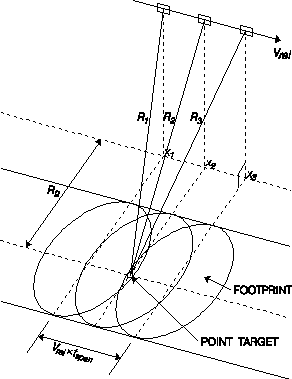
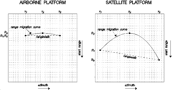
Figure 7. Hyperbolic curve traced by a point target in the azimuth-slant range plane.
When two waves are not synchronous with each other, they are said to be out of phase.
The phase difference is measured in radians or degrees. For instance, if the wave A's
crest occurs at the same time as wave B's trough, the phase difference is
 (or 180º).
Figure 8 illustrates further examples.

Figure 8. Phase differences between two waves.
The phase difference, in radians, between the transmitted and received signal will be

where Figure 9, shows that the range is

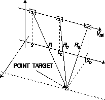
Figure 9. Quadratic relation between range and time for a target within the radar beam.
Using the Taylor series to expand this around the position xc for the slant range Rc gives

when truncated to the second order. Assuming that Rc and R0 are approximately equal for narrow beam radars, the Doppler frequency shift is
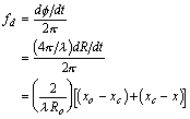
By assuming that the Doppler frequency shift is constant only until the
quadratic term adds a value of  / 4 to
  ,
then the window for observing the waveform is confined to a distance of
xwindow, where

and so

Therefore the time window is

Therefore, the new azimuth resolution is

A SAR processor which uses this technique is known as unfocused SAR. This technique does not account for the variable rate of phase change, but still manages to produce a resolution much smaller than that for real aperture radars. For example, using the above equation, the resolution for RADARSAT would be

as opposed to the real aperture limit of 3.0 km.
The resolution can get even better, however, by using a focused SAR processor which
accounts for the nonlinear phase change. This technique uses all the data collected
during the time that the target is within the beam. The quadratic phase
 is adjusted such that all the return signals due to the
target at x0 (see Figure 9) are added
coherently. Any returns from targets not at x0
will not agree with the adjusted returns so they will cancel. Thus the returns
from the target at x0 will dominate the returns from
other targets with the same range but not at x0.
With a few assumptions, this technique results in an azimuth resolution
approaching La / 2, which is what we calculated
before, assuming a constant phase.
Geometric Distortions
At first glance, a SAR image may seem to closely resemble an optical image. Closer inspection, however, reveals striking differences which can be used, given knowledge of how radar interacts with ground features, to provide a wide spectrum of information about the targets. The most obvious difference from an optical image is the geometric distortion produced due to the depression angle and the height or slope of the target.Slant vs. Ground Range
When terrain is imaged using an optical sensor such as a camera, the image can be thought of as a central perspective projection--all of the terrain points have projection lines passing through a central point on their way to their corresponding image points, as in Figure 10a. The situation for a SAR is very much different, however, in that ground objects will be placed into locations on the image line as a function of their distance from the antenna--not as a function of their distance from each other on the ground. Figure 10b shows that the projection lines are concentric circles around the antenna, due to the spherical spreading of EM pulses.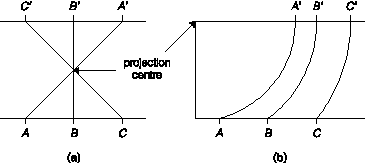
Figure 10. Image projections for (a) optical and (b) SAR imaging systems.
Suppose you are imaging objects A and B, separated a distance on the ground, as shown in Figure 11. Because the SAR is viewing from an angle, the two points will look closer together than they actually are. Since angle ACB is approximately 90º, we can say that Dg in slant range presentation is

so that the distance in slant range presentation is always less than in the corresponding
ground range projection. As the depression angle  gets larger,
Ds gets smaller for a given distance
Dg. Thus the slant range presentation
compresses the terrain features in the near range more than in the far range.
This has the effect of greatly stretching the ground range projection near
the nadir where
  approaches 90º.
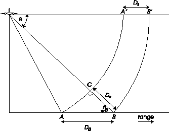
Figure 11. Image of points A and B in slant range and ground range presentations.
The ground range presentation is used when one wishes to match the image with known target locations (i.e. geocoding the image) on the ground. EarthView is able to convert an image from slant range to ground range and visa versa, taking into account the curvature of the Earth for satellite imagery.
Relief Displacement
Imaging a target on top of a vertical structure height h above the ground results in a relief displacement, that is, the target is displaced a distance of rs in the original slant range presentation of the image, as shown in Figure 12.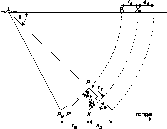
Figure 12. Relief displacement due to a vertical structure.
The relief displacement rg is equal to the
distance  , however for a small enough value of h,
we see that PgX
  P'X. Thus we can estimate the relief displacement in ground
presentation as

and in slant range presentation as

Thus the relief displacement is proportional to the height of the vertical structure and increases the closer that structure is to the nadir line.
Lay Over
The direction of relief displacement is different for optical and radar systems. A camera sees the relief displaced away from the nadir point while the SAR see the relief displaced towards the nadir line. This is illustrated in Figure 13.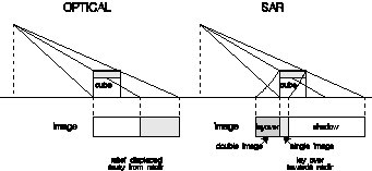
Figure 13. A comparison of relief displacement for (a) optical and (b) SAR systems.
Shadows
The other effect of vertical structures is to produce shadows in the SAR image. Figures 12 and 13 illustrate this effect quite well. Because the radar beam is at an angle, there will be a region of ground behind the vertical structure that the beam cannot reach. Thus for the time period corresponding to that ground area, no echoes will be returned. This results in a black area on the image which is called a shadow. From Figure 12, the length of the shadow is calculated as
in ground range presentation and

in slant range presentation. Thus the length of the shadow is proportional to the height of the vertical structure and increases the further away that structure is from the nadir line or the lower the SAR antenna is.
Image of a Slope
The effects of imaging sloping terrain with radar are illustrated in Figure 14. Due to the vertical height, relief displacement, lay over and shadows can result, depending on the steepness of the slope. Slopes facing the nadir line can exhibit the effects of (a) lay over, (c) foreshortening and the in-between case (b) for which the front slope appears only as a line. Case (b) only occurs when the slope is parallel to the nadir line and the elevation angle equals the slope angle
  exactly.
Slopes facing away from the nadir line can be (a) fully imaged, (c) hidden in the radar shadow or (b) strangely imaged as the radar beam just skims along the surface. For case (b), slight irregularities on the slope's surface would have magnified effects. For instance, a bump near the peak would block the radar from the rest of the slope causing a shadow to appear in the image.
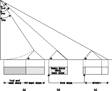
Figure 14. Image effects produced by sloping terrain.
All of these slope effects can be found in Figure 15--a subsection of the SAR image
82LWERS1 ( ESA) from the ERS-1 satellite, provided
with EarthView.
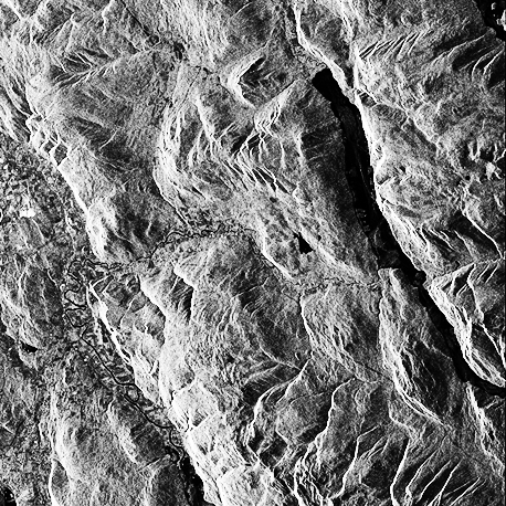
Figure 15. ERS-1 SAR image illustrating the effects of uneven terrain
( ESA).
ESA).
Surface Interaction with the Radar Beam
When an electromagnetic wave reflects off a surface, three basic properties of the surface come into play--the dielectric constant (or permittivity ), the roughness (rms height relative to a smooth
surface) and the local slope.
Assuming that the EM wave is traveling through a medium that is homogeneous (properties do not vary from point to point), isotropic (properties are the same in all directions from any given point) and non-magnetic, then from Maxwell's equations we can express the complex electric field vector as

where A is the amplitude vector, z is the distance traveled in time
t and  is a phase offset. The angular frequency
 is
is

where fc is the carrier frequency (the
frequency emitted from the antenna) and  is the
wavelength. The expression for k' is

where k is the wavenumber and  r
is the relative permittivity (also called the dielectric constant) of the
medium (
 r =
r =
 /
/  0
where
  is the permittivity of the medium and
 0 is the permittivity of
free space). It should be noted that
 r is a function of
the frequency of the EM wave. The relative permeability
 r has been assumed to be
equal to 1 which is accurate enough for microwave frequencies.
The polarization of the electric field E is the direction of the amplitude vector A at some instant in time. For a linearly polarized wave, the direction of A is fixed in one plane relative to the direction of propagation. An elliptically polarized wave has an electric field consisting of two different components oriented along orthogonal axes such that

resulting in the total amplitude vector A slowly rotating about the
z-axis. If Ax =
Ay and
[ 1 -
1 -
 2] =
2] =  /2,
then the wave becomes circularly polarized.
An EM wave interacting with a surface is called scattering. There are two types—surface scattering and volume scattering. Surface scattering occurs at the interface between two different homogeneous media such as the atmosphere and the Earth's surface. Volume scattering is the result of interaction with particles within a non-homogeneous medium.
Surface Scattering
A smooth surface acts as a mirror, reflecting the EM wave at an angle equal and opposite to the incidence angle .
Thus a smooth level surface is seen as black in the
SAR image since the echoes never reach the antenna. The Rayleigh criterion defines a
surface as smooth if

where h is the surface roughness, defined as the root-mean-square (rms) height relative
to a perfectly smooth surface,  is the
wavelength of the wave and
  is the angle of
incidence. Peake and Oliver (1971) modified this criterion by defining upper and lower
values of h for surfaces of intermediate roughness to obtain a smoothness criterion of

Using the Rayleigh criterion, for instance, when RADARSAT is operating at 5.3 GHz with an incidence angle of 50º, level terrain with h < 9 mm will show up as solid black.
Specular Scattering
Any returns from a smooth level surface are due to specular scattering, in which the EM wave's angle of incidence is equal and opposite to the angle of reflection and the transmission through the surface obeys Snell's Law:
where n and n' are the index of refractions of the two mediums,
 is the angle of incidence and
  '
is the angle of refraction, shown in Figure 16. However, the index of
refraction is equal to

For a non-magnetic medium,  r
= 1, and for air,
  r
r
 1. Therefore Snell's Law becomes


Figure 16. Specular scattering mechanism.
For the perfect specular reflector, radar returns (backscatter) exist only near vertical incidence (due to a 90º depression angle or the slope of the surface) and the reflected energy is localized to a small angular region around the angle of reflection. Even for non-vertical incidence, however, backscatter can exist for a rough subsurface if the radar is capable of penetrating deep enough. Figure 16 illustrates how it is possible to image a subsurface (i.e. the surface of a different medium below the top surface) that would otherwise be invisible to optical sensors.
Bragg Scattering
For a homogeneous medium with a slightly rough surface (an rms height variation of less than /8), the scattering can be described using the Bragg model.
The surface features can be described in terms of a spatial spectrum. Any section of that spectrum
which resonates with the incident wave will produce a strong backscatter. Thus, a
strong return will result from surface variation patterns at wavelengths of

where the dominant return is due to the wavelength  for which n=1. At steep incidence angles, the backscatter is
usually a combination of both specular and Bragg scattering.
The Bragg model is useful for describing the backscatter from the ocean surface. Water has a large dielectric constant making volume scattering impossible (see section 2.5.2). The periodic structure of ocean waves resonate well with radar waves, showing up as periodic bands on the image. When imaging slightly rough terrain with little vegetation, the Bragg model can be used to classify rock types and ages based on the surface roughness.
Volume Scattering
Natural surfaces usually result in both surface scattering and volume scattering. Natural surfaces are generally inhomogeneous, meaning they are composed of different mediums. Depending on the radar wavelength and the permittivity of the media, the EM wave will penetrate a certain depth beneath the surface. The depth at which the refracted portion of the wave will be attenuated by 1/e of its original power at the surface boundary is
where the relative dielectric constant is given by the complex number
 r =
r =
 ' + i
' + i '' and
 ''/
''/ '
must be less than 0.1 for the equation to be valid.
Since every type of material has its own characteristic dielectric constant
 r, the media
are dielectrically variant which results in volume scattering. If the different media are
mixed together in a mostly random manner, the backscatter will be in many directions.
The fraction of the incident wave that is reflected back to the antenna, then, depends on
the shape, density and orientation of the different media as well as on the relative
permittivity between them.
Complex Dielectric Constant
The complex dielectric constant of most natural materials, when dry, is between 3 and 8 (for a typical radar frequency). For such values, the penetration depth is quite large and the reflectivity correspondingly small. The dielectric constant for water, on the other hand, is around 80 (for the same frequency) resulting in high reflectivity from the surface and almost no penetration. The complex dielectric constant for a material varies almost linearly with the moisture content per unit volume. The higher the moisture content, the lesser the penetration depth is and the greater the reflectivity is. The observed variation in reflectivity from natural surfaces is mainly due to the moisture content of the vegetation or soil. Thus an analysis of the returns for a specific region allows for classification of the type of soil or vegetation being imaged.Since the dielectric constant depends on the frequency of the EM wave, so does the reflectivity. The higher the frequency (or the lower the wavelength), the lesser the penetration is. If one is imaging a forest, for example, using a high frequency will result in surface scatter from the top of the vegetation canopy while a lower frequency would allow the EM waves to penetrate the canopy, producing volume scattering from the leaves, branches, trunks or ground.
Polarization
The polarization of an EM wave refers to the orientation of the electric field intensity vector. A SAR usually transmits a wave such that it is horizontally polarized. Most of the received energy is still horizontally polarized, however a small portion of it may be depolarized through interaction with the terrain, creating many different components at various angles of polarization.Using a filter at the antenna, all polarizations can be screened out except for the desired polarization--either horizontal or vertical. The HH (transmit and receive horizontal) configuration is called the like-polarized return while the HV (transmit horizontal and receive vertical) configuration is called the cross-polarized return. The HV return requires a much higher antenna gain than the HH due to its much smaller energy.
The images produced by these two returns may differ due to the differences between the scattering processes for each. Depolarization, for instance, is usually explained in terms of volume scatter or multiple reflections. At short wavelengths, when the terrain can be considered very rough, like- and cross-polarized images are almost identical. At longer wavelengths, however, when the terrain is considered relatively smooth, noticeable differences stand out. This has resulted in limited geological application in identifying rock types.
Some of the new polarimetric SARs are capable of transmitting and receiving both horizontally and vertically thus allowing HH, HV, VH and VV returns all at the same time. Mathematical analysis of these returns can create a geometric basis which can be used to synthesize the image for any possible transmit/receive polarization for the entire 360º spectrum. Certain objects, especially those man-made, have been found to stand out at a specific transmit/receive polarization, thus making their detection easier in the future.
Speckle
All SAR images inherently contain noise, whether due to the hardware or to stray radiation from other sources or to the phenomenon known as speckle. Speckle manifests itself in the image as the apparently random placement of pixels which are conspicuously bright or dark. It arises from the requirement that a SAR image be formed using coherent radar--radar that can provide a Doppler resolution.A single resolution cell, or pixel, corresponds to an area of a certain size on the ground. Within that area, there exist many different targets, or scatterers, which provide the surface texture necessary for backscatter. Even though the area may be something on the order of 15 x 15 metres, the wavelength of the EM wave may be only several centimetres--capable of interacting with each individual scatterer. These multiple interactions produce echoes which interfere with each other in either a constructive or destructive manner. Constructive interference results in a strong return signal and a bright pixel in the image. Destructive interference results in a weak return signal and dark pixel in the image.
By interpreting speckle as a random noise effect, various methods can be used to reduce speckle. Neighbouring pixels can be averaged together to spread the aberration out at the cost of resolution. This is known as a multiple look image. EarthView provides a median filter, in which you can specify the size of the window of pixels to average, and a LUM Filter which uses a completely different rank-order-based technique. EarthView provides other filters for speckle reduction (Lee, Frost, MAP and Refined MAP) which smooth the data without blurring it as the median filter does.

